Writing a Software Rasteriser: 2.Triangle Rasterisation
Memory Safety is Important
Before we get started let’s talk about memory safety. In the last post we used a little bit of unsafe to interface with C and to index the framebuffer. Unsafe code is well, unsafe, so as a good Rust programmer you must be very sure that when you use unsafe, you guarantee program correctness. Were you looking really carefully in the last post? When we indexed the buffer last time, we used the ptr::add() function which is marked unsafe. Whenever you use an unsafe function you should double check the documentation to see why it is unsafe and ensure that you can guarantee you are not breaking any of the rules assumed for safe usage.
I recommend that when you use unsafe you leave a comment to say why your usage is still considered sound. Let us do that now for Framebuffer::set(), addressing the three dot points the documentation states.
    pub fn set(&mut self, x: usize, y: usize, colour: Colour) {
        let pos = (x + self.x_offset as usize) + (y + self.y_offset as usize) * self.line_length as usize;
        // Safety: ???
        // Safety: ???
        // Safety: We do not rely on wrapping
        unsafe {*self.buffer.add(pos) = colour.convert(self) }
    }
Uhhhh… We broke two of the rules specified by the function! If you draw to 8000x8000 you will probably set some memory outside of the framebuffer which is very much undefined behaviour, a buffer overflow! We should start by ensuring that we do not write out of bounds.
    pub fn set(&mut self, x: usize, y: usize, colour: Colour) {
        let pos = (x + self.x_offset as usize) + (y + self.y_offset as usize) * self.line_length as usize;
        if pos >= self.buffer_len / std::mem::size_of::<u32>() {
            panic!("Pixel ({}, {}) is out of framebuffer bounds", x, y)
        }
        // Safety: We have checked that the buffer access is in-bounds
        // Safety: ???
        // Safety: We do not rely on wrapping
        unsafe {*self.buffer.add(pos) = colour.convert(self) }
    }
But what about that last guarantee? Well on x86_64 we are fine since pos is now limited by buffer_len which originated from a u32 and is therefore never going to overflow an isize since x86_64 has a virtual address space of 48 or 52 bits, leaving us quite a bit of extra room. There is still the (slight) possibility of breaking this guarantee on other platforms so we should check it just in case on other platforms. To ensure we don’t waste on time on the unnecessary check on x86_64 we use conditional compilation.
    pub fn set(&mut self, x: usize, y: usize, colour: Colour) {
        let pos = (x + self.x_offset as usize) + (y + self.y_offset as usize) * self.line_length as usize;
        if pos >= self.buffer_len {
            panic!("Pixel ({}, {}) is out of framebuffer bounds", x, y)
        }
        #[cfg(not(target_arch="x86_64"))]
        if pos * std::mem::size_of::<u32>() + self.buffer as usize >= isize::MAX {
            panic!("Framebuffer cannot be indexed due to platform addressing constraints")
        }
        // Safety: We have checked that the buffer access is in-bounds
        // Safety: Result does not overflow an isize
        // Safety: We do not rely on wrapping
        unsafe {*self.buffer.add(pos) = colour.convert(self) }
    }
Alright, now it will crash the program when we can’t uphold the guarantees rather than just causing undefined behaviour which could cause something much worse than a crash.
Drawing Triangles
With that out of the way it is time to draw our first triangle. First, let us add the notion of a triangle to our maths library since we might want to do higher-level operations on them in the future. For now it will be a simple wrapper class over an array of Vector2, nothing new.
pub struct Tri(pub [Vector2; 3]);
impl Deref for Tri {
    type Target = [Vector2; 3];
    fn deref(&self) -> &Self::Target {
        &self.0
    }
}
impl DerefMut for Tri {
    fn deref_mut(&mut self) -> &mut Self::Target {
        &mut self.0
    }
}
Now we can add our drawing method to Framebuffer.
pub fn draw_tri(&mut self, tri: Tri) {
    // What now?
}
There are a few ways to draw a triangle, lets weigh up the pros and cons of some.
The simplest one that has probably come to your mind is to just to fill the box around the triangle from (min(x), min(y)) to (max(x), max(y)) and test each pixel for being inside the triangle.
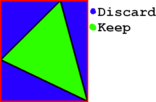
This approach is simple and only draws over each pixel once, however, it wastes a lot of time checking unused pixels and the check itself is not very cheap either.
We may also follow the line down, stepping down by the gradient each time, a simple addition, and then drawing that line horizontally across the screen.
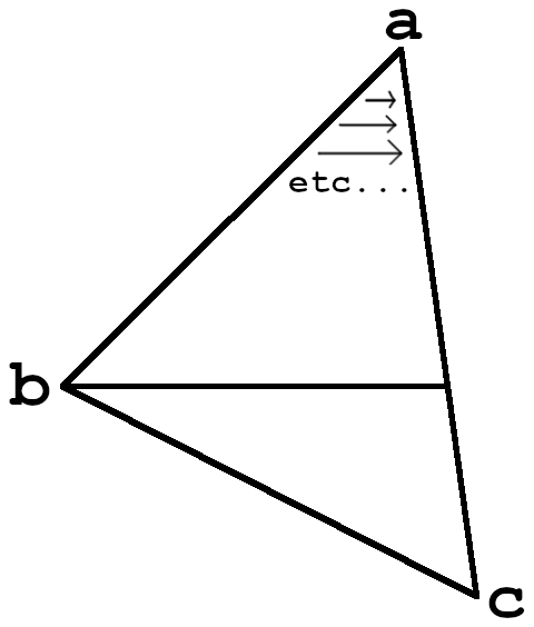
This approach is slightly more complicated and requires maybe segmenting the triangle, but it does draw each pixel exactly once, and only if it is actually inside the triangle.
Another approach would be to draw lines from point a to progressively accross the line BC. The line drawing algorithm used is generally Bresenham’s algorithm.
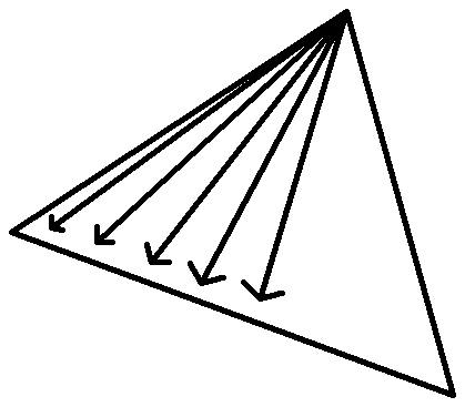
As is obvious there is a lot of overdraw near the convergence point. Drawing a pixel more than once is not much of an issue now, sure, but in the future if we want to draw slightly transparent objects and do alpha blending then the overdraw would mean that at best we need a second buffer to allow the tracking of draws so we can tell if it is one of the extra draws or not.
We will take the second option since the only compromise is to our laziness. If you want more information on these three approaches this page does a decent job explaining things. My approach to their “standard algorithm” is slightly different as I don’t completely split the triangle into two but the idea is the same.
The first step is to sort the points by height so that we can make certain assumptions, such as which edge is the highest and which point is in the middle. All of the code for now is inside the Framebuffer::draw_tri() method.
let mut a = 0;
let mut b = 1;
let mut c = 2;
if tri[a].y > tri[b].y {
    std::mem::swap(&mut a, &mut b)
}
if tri[a].y > tri[c].y {
    std::mem::swap(&mut a, &mut c)
}
if tri[b].y > tri[c].y {
    std::mem::swap(&mut b, &mut c)
}
Because of borrowing rules we can’t swap elements of an array directly, since that would be a mutable access to the same object more than once. Indexing by a, b and c is more clear anyway. Next we calculate the vectors for each edge as well as the location of b on the highest edge by the same height. We get the proportion of the height of the top edge to the hight of high edge, top_edge.y / high_edge.y, next we travel along the x position of the high edge by that proportion, * high_edge.x before translating it back to a point, rather than a line, + tri[a].x. The way in which we travel down the lines also depends on the handedness of the triangle, so we determine if its high edge is on the left or right of the other edges and midpoint.
let high_edge = tri[c] - tri[a];
let top_edge = tri[b] - tri[a];
let bottom_edge = tri[c] - tri[b];
let midpoint_x = tri[a].x + top_edge.y / high_edge.y * high_edge.x;
let left_triangle = midpoint_x < tri[b].x;
Next we actually need a way to travel down the line. The easiest and most efficient way is to just calculate the amount to go across by for each step down, or the inverse gradient. This does however introduce an additive floating point error and a bit of inaccuracy which may make our triangle look a little funny in the extremes, but it is worth it since the alternative includes heavy computations for every pixel. The direction we step depends on if it is a left or right triangle so we switch to match. We also only want to draw portion above the midpoint if there actually is a top portion.
if tri[a].y as usize != tri[b].y as usize {
    let (l_grad, r_grad) = if left_triangle {
        (high_edge.inverse_gradient(), top_edge.inverse_gradient())
    } else {
        (top_edge.inverse_gradient(), high_edge.inverse_gradient())
    };
We didn’t think to add an inverse gradient function back when we created our maths library so we will do so once we are done here. Luckily it is super simple.
To draw down to the mid point we then iterate through the y coordinates from point a to b and draw each line by plotting pixels from the x_start to the x_end then moving them by the l_grad and r_grad gradients respectively.
let mut x_start = tri[a].x;
let mut x_end = x_start;
for y in tri[a].y as usize .. tri[b].y as usize {
    for x in x_start as usize .. x_end as usize {
        self.set(x, y, Colour(0xFF0000FF))
    }
    x_start += l_grad;
    x_end += r_grad;
}
To now draw the lower half of the triangle we reset the start and end points, for both alleviating error and in-case the top half didn’t have any height, calculate the new gradient then do the nested loop with gradient updates again. Once again, we only do so if the lower half of the triangle exists.
if tri[b].y as usize != tri[c].y as usize {
    let mut x_start = tri[b].x;
    let mut x_end = midpoint_x;
    if left_triangle {
        std::mem::swap(&mut x_start, &mut x_end)
    }
    let (l_grad, r_grad) = if left_triangle {
        (high_edge.inverse_gradient(), bottom_edge.inverse_gradient())
    } else {
        (bottom_edge.inverse_gradient(), high_edge.inverse_gradient())
    };
    for y in tri[b].y as usize ..= tri[c].y as usize {
        for x in x_start as usize .. x_end as usize {
            self.set(x, y, Colour(0xFF0000FF))
        }
        x_start += l_grad;
        x_end += r_grad;
    }
}
And that should be enough to draw a triangle. Let’s add the Vector2::inverse_gradient() method then create a quick test scene.
    /// The inverse of the gradient of the line given by the run divided by the rise of the line
    /// ```rust
    /// use tendon::*;
    /// let v = Vector2 { x: 8.0, y: 4.0 };
    /// let dif = v.inverse_gradient() - 2.0;
    /// assert!(dif.abs() < 1e-10);
    /// ```
    pub fn inverse_gradient(self) -> f64 {
        self.x / self.y
    }
I hope you have been doing your documentation and testing!
Now lets actually show it to the screen. In src/main.rs we can open the framebuffer then draw a triangle.
mod fb;
mod maths;

use maths::*;

fn main() {
    let mut fb = fb::Framebuffer::new().unwrap();
    fb.draw_tri(Tri([
        Vector2 { x: 150.0, y: 50.0 },
        Vector2 { x: 75.0, y: 100.0 },
        Vector2 { x: 200.0, y: 130.0 },
    ]));
}
To see it we need need to be in the framebuffer console (or tty, ctrl-alt-f2 when a display server is running) so that our window manager doesn’t draw over it. If we execute cargo run now we will see our little triangle. If you have errors make sure you are in the video group so that you have permission to open /dev/fb0.
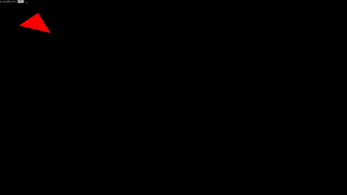
What a perfectly fine triangle. It isn’t too pretty though, we haven’t considered colours or textures yet. For our game we will only be wanting textured surfaces, which saves us having to implement different draw_tri functions, our equivalent to fragment shaders. For a textured surface you need two things, texture coordinates, normally named UVs and a way to get a pixel colour from a texture, normally called a texture sampler. But before that you were probably wondering how to take a screenshot of your triangle, so let’s do that first.
First we need a way to Framebuffer::get() a pixel value from the framebuffer, this is more or less the same as Framebuffer::set().
pub fn get(&self, x: usize, y: usize) -> u32 {
    let pos = (x + self.x_offset as usize) + (y + self.y_offset as usize) * self.line_length as usize;
    if pos >= self.buffer_len {
        panic!("Pixel ({}, {}) is out of framebuffer bounds", x, y)
    }
    #[cfg(not(target_arch="x86_64"))]
    if pos + self.buffer as usize >= isize::MAX {
        panic!("Framebuffer cannot be indexed due to platform addressing constraints")
    }
    unsafe { *self.buffer.add(pos) }
}
We also need to convert the colour to useable RGB components, again this is just the opposite of our previous experience in Colour. I’m using an associated function so that we don’t conflate a Colour with a raw u32 value.
pub fn u32_to_rgb(colour: u32, fb: &Framebuffer) -> (u8, u8, u8) {
    (
        (colour >> fb.red_offset & 0xFF) as u8,
        (colour >> fb.green_offset & 0xFF) as u8,
        (colour >> fb.blue_offset & 0xFF) as u8
    )
}
You should add a doc comment and test to that. Next we need a way to save to a common file format. Writing an image encoder is very much out of scope for us, and there is a crate that can do a better job than us anyway, so let’s just add image to our Cargo.toml
[dependencies]
image = "0.23"
Make sure to use the latest version available to you and make any necessary changes when using the library. Finally we dump the image to disk by creating an image buffer then converting each pixel in the framebuffer to the matching RGB values and setting them in the image. image can save the image buffer to disk for us, we just need to propagate the potential errors to our future selves.
pub fn dump<P: AsRef<Path>>(&self, path: P) -> image::ImageResult<()> {
    let mut img = image::ImageBuffer::new(self.x_res, self.y_res);
    for (x, y, pixel) in img.enumerate_pixels_mut() {
        let (r, g, b) = Colour::u32_to_rgb(self.get(x as _, y as _), self);
        *pixel = image::Rgb([r, g, b])
    }
    img.save(path)
}
We also need two new variables to be saved when we open the framebuffer so we know the resolution of the image to save. We carefully modify the Rust structure
pub struct Framebuffer {
    buffer: *mut u32,
    buffer_len: usize,
    bytes_per_pixel: u32,
    red_offset: u32,
    green_offset: u32,
    blue_offset: u32,
    x_offset: u32,
    y_offset: u32,
    x_res: u32,
    y_res: u32,
    pub line_length: u32
}
and the C structure to match so that we avoid undefined behaviour.
struct fb {
    unsigned* buffer;
    size_t buffer_len;
    unsigned bytes_per_pixel;
    unsigned red_offset;
    unsigned green_offset;
    unsigned blue_offset;
    unsigned x_offset;
    unsigned y_offset;
    unsigned x_res;
    unsigned y_res;
    unsigned line_length;
};
And we also make sure to set the x and y resolutions in fb_create() on the C side too.
fb.x_res = var_info.xres;
fb.y_res = var_info.yres;
Texture Mapping
Now we already have image which will be useful when we want to load textures for texture mapping in a moment. Texture mapping is done by interpolating between texture coordinates at each vertex of the triangle. This means we need another 3 Vector2’s to store all that information. Additionally we need that aforementioned sampler, so let’s edit the definition of Framebuffer::draw_tri(). Our sampler is probably going to borrow a reference to some image data so we include a lifetime annotation to say we keep the sampler only for the duration of the function.
pub fn draw_tri<'a>(&mut self, tri: Tri, uvs: Tri, sampler: &Sampler<'a>) {
    // ...
}
Let’s start with the sampler since it’s design might influence our function a little more than the texture mapping logic. A sampler is a view into some texture data with a function to retrieve a pixel, but remember, the coordinates for pixels are not integer indices, but rather float indices, an absolute necessity since we will be doing transformations such as perspective projection, further we will want to map texture coordinates between 0 and 1 to make them texture size agnostic. The interpolation of pixel data to best fit our sub-pixel texture coordinate is called texture filtering, if you play games you may recognise the name along with options such as bilinear, trilinear and anisotropic filtering. These techniques smooth out values to make them feel less blocky, which is great when your game needs realistic looking textures, but for our programmer art we will be wanting to use nearest neighbour filtering which does no interpolation between pixels, instead choosing a single pixel colour, causing no smoothing to be done at all. When you hear nearest-neighbour filtering you will probably hear “Minecraft Graphics” alongside it. Conveniently enough for us nearest neighbour is about as simple as it gets. If you want bilinear or trilinear filtering instead Scratchapixel has a good tutorial. With trilinear the third dimension, or backface, is to interpolate with mipmaps which are minimized images so that we can improve quality when zooming the texture out.
pub struct Sampler<'a> {
    pub texture: &'a Texture
}
impl<'a> Sampler<'a> {
    /// Get the pixel nearest `x` and `y`
    pub fn sample(&self, x: f64, y: f64) -> Colour {
        // Nearest Neighbour logic
    }
}
We also need to define the owned texture, that is, the buffer which is not borrowed, as well as a method to index it by integer values. Soon we will also add a function to load it from disk.
pub struct Texture {
    pub buffer: Vec<Colour>,
    pub width: usize,
    pub height: usize
}
impl Texture {
    pub fn get(&self, x: usize, y: usize) -> Colour {
        #[cfg(debug_assertions)]
        if x >= self.width {
            panic!("Cannot index texture of width {} by x index {}", self.width, x)
        }
        self.buffer[x + y * self.width]
    }
}
We use conditional compilation to make sure accesses are in bounds on the x axis here in debug mode only. In release mode we can accept the visual artefact for the speed since Rust will still protect from a bad memory access and panic and we are not supposed to index out of bounds anyway. Now to add the texture filtering itself in Sampler::sample().
self.texture.get(
    f64::floor(x * self.texture.width as f64) as usize,
    f64::floor(y * self.texture.height as f64) as usize
)
Well that was anticlimactic. It won’t be particularly fancy giving us aliasing and some pretty terrible artefacts when zooming the texture out, but it will work well enough for now. Or will it? If we extend our triangle but don’t want it to stretch the texture so we scale the UV coordinates with it we would end up with a UV outside of the range 0 to 1. Rather than just panicking here we should either clamp to a particular border colour or wrap the texture so that it repeats. We will go with wrapping since that is very handy for large floor or wall textures. Since we want it in the range 0 to 1 we can simply take the fractional component. Conveniently since we are wrapping it doesn’t matter that we are discarding 1.0 exactly since it wraps to 0.0 anyway. The f64::fract() method in Rust keeps the sign bit so we must also use f64::abs().
self.texture.get(
    f64::floor(x.fract().abs() * self.texture.width as f64) as usize,
    f64::floor(y.fract().abs() * self.texture.height as f64) as usize
)
Next up is interpolating texture coordinates for each pixel we texture. For the record, each pixel on a rasterised triangle is called a fragment and it is given its colour by a fragment shader, a program that runs on the GPU which may do things like texture sampling. We have a fixed pipeline with no need for different fragment shaders, we only care about textured surfaces so far. The interpolation of values from triangle vertices is normally done using a Barycentric coordinate system. Simply put, each of the UVs is scaled to its correct proportion for that fragment. The sum of proportions is obviously 1. Each of these proportions can be seen as the percentage of the whole triangle that sub-triangles given by the division around our fragment location.
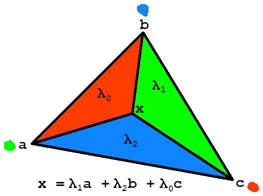
Each of the lambdas (λ) corresponds to the percentage of area that each sub-triangle takes from the total area. This is the proportion, or weight, that we apply to a vertex when interpolating. This means when the green triangle covers all of the area for a λ value of 1, the fragment is on point a. This is why we use the triangle opposite a point. The values at each vertex are weighted, or scaled, then combined to do the interpolation, represented mathematically by p = x*a + y*b + z*c where x, y and z correspond to the repective area proportions and p the fragment colour. I recommend you check out Scratchapixel’s awesome tutorial on barycentric coordinates for a more in-depth look. Now that means we need to find the area of each triangle, a feat easily achieved using the scalar triple product. At a first glance this looks kind of useless, we don’t care about the volume of a parallelepiped at all! But think back, how do we calculate the area of a triangle? Using 0.5 * base * height, or half the area of a parallelogram, and a parallelogram is just a flat parallelepiped. Triple product is pretty easy to calculate since we have very simple definitions of both dot and cross product which use only addition, subtraction and multiplication. What’s more is that we are using constant 1’s and 0’s since we are converting 2d vectors to 3d vectors and using a constant height of 1 for the parallelepiped so we can simplify the equation a lot. When doing some mathematics nothing beats a pen and paper so let’s pull some out and get to work.
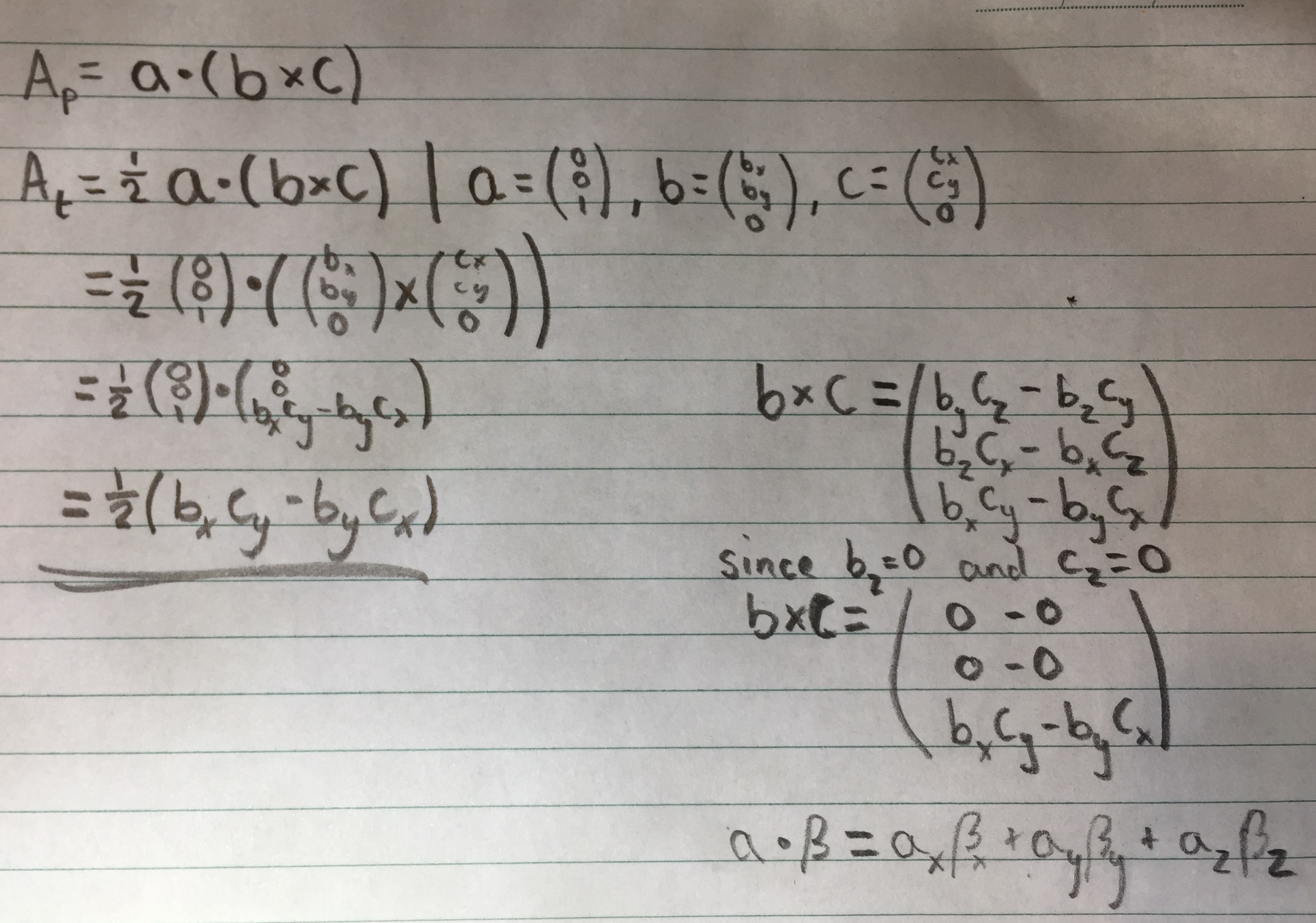
Pretty simple right. Now we can easily translate this to Rust in Vector2::area_tri(). Keep in mind this gives us the signed area while we only care about the actual area.
pub fn area_tri(self, other: Self) -> f64 {
    (self.x * other.y - self.y * other.x).abs() * 0.5
}
This will be the last reminder so hopefully it is drilled in by now, don’t forget to document and add tests. Now we can add a function, Tri::interpolate() which takes the geometry, the UVs to interpolate and the position of the fragment. We need to then calculate the areas of the sub triangles and total area using the edge vectors since these do not contain a translation, just the length and direction. To get the area we calculate the two edge vectors enclosing the area, being mindful of the direction we give them. I name each edge by the point it is opposite which makes it obvious which area it corresponds to and also avoids slightly more confusing AB line names. We can choose the internal edge by noting the direction of the first edge, which I recommend you draw on paper.
    pub fn interpolate(&self, other: &Tri, x: f64, y: f64) -> Vector2 {
        let p = Vector2 { x, y };
        let edge_a = self[1] - self[2];
        let edge_b = self[0] - self[2];
        let edge_c = self[0] - self[1];
        let area_a = edge_a.area_tri(p - self[2]);
        let area_b = edge_b.area_tri(p - self[2]);
        let area_c = edge_c.area_tri(p - self[1]);
        // More to come...
    }
Next we must convert the area to a proportion of the total area so we can use it as a weighting. I use edge_a and edge_b because they point in the correct direction to encompass the areas of the triangle.
    let total_area = edge_a.area_tri(edge_b);
    let weight_a = area_a / total_area;
    let weight_b = area_b / total_area;
    let weight_c = area_c / total_area;
These weights are our lambda values. We can now do the interpolation using these weights. Because UV coordinates are 2 dimensional we interpolate twice. If we were interpolating colours we would do it thrice or more.
Vector2 {
    x: weight_a * other[0].x + weight_b * other[1].x * weight_c * other[2].x,
    y: weight_a * other[0].y + weight_b * other[1].y * weight_c * other[2].y,
}
The final cog to put in place is to actually use the interpolated coordinates and sample when setting a pixel.
In Framebuffer::draw_tri() we now change the two occurrences of
self.set(x, y, Colour(0xFF0000FF))
to
let uv = tri.interpolate(&uvs, x as _, y as _);
self.set(x, y, sampler.sample(uv.x, uv.y))
All that is left to do now is load a texture to draw. Before doing that I couldn’t miss the opportunity to do the classic computer graphics equivalent of “Hello, World!”.
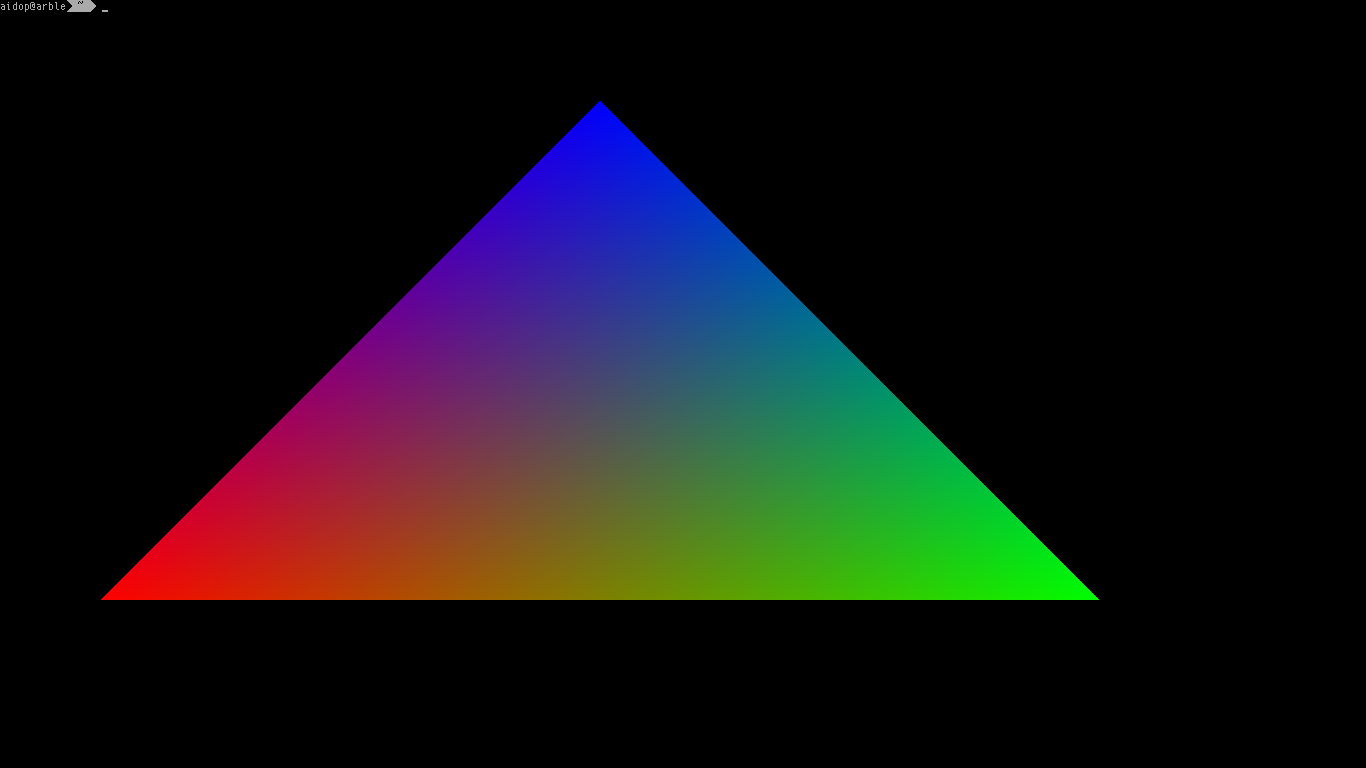
All you have to do is use a Vector3 of RGB colours instead of a Vector2 of texture coordinates and interpret the interpolated value as a colour instead of coordinates. If you still need some guidance to do this yourself see this commit.
Back to implementing texture mapping, we define Texture::load() as
pub fn load<P: AsRef<Path>>(path: P) -> image::ImageResult<Self> {
    use image::{GenericImageView, Pixel};
    let image = image::open(path)?;
    let (width, height) = image.dimensions();
    let buffer = image.pixels().map(|(_, _, p)|
        Colour(u32::from_be_bytes(p.to_rgba().0))
    ).collect();
    Ok(Self {
        buffer,
        width: width as _,
        height: height as _
    })
}
Which is just using the image crate to load an image in any supported format, getting its size, and converting each colour to our native-endian representation before collecting into an owned buffer. We use the function u32::from_be_bytes() to because we want a native endian 0xRRGGBBAA from [r, g, b, a] of which the latter is the big-endian representation of the former.
That is all! We can test it now by loading a texture and constructing some test-case triangles which test some of the possible edge cases, such as wrapping. It is just a bunch of coordinates which I won’t waste space on here so see the commit instead. I used the GIMP capsicum as my testing image.
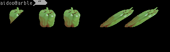
It was a lot of effort but how amazing is that. Don’t worry if it is super slow either, most of the delay right now is from our inefficient texture loading and, if you are taking a screenshot, framebuffer saving. Neither of these actions are on the hot path so we can live with slow startup or a slight screenshot freeze. I also haven’t run it in release mode yet which introduces a lot of optimisations to speed things up.
There are many things I have neglected to do in this implementation. For example, our triangle rasteriser makes no guarantee about shared edges which means we could see thin gaps between triangles on complex geometry. We are also still using screen coordinates rather than normalised device coordinates (NDC) and we haven’t implemented clipping for when we try to draw a triangle offscreen. We also don’t have a depth buffer to go along with the 3d normalised device coordinates, however, as we will be using binary space partitioning for level drawing a depth buffer will not actually be necessary. Remember, we have only implemented the most basic triangle rendering primitive, everything else will be layered upon what we have done so far.
It should be noted that this implementation of Barycentric interpolation is not appropriate for use in 3-dimensional space as it only calculates the area in 2-dimensional screen space. There is a fair bit to know about the different coordinate spaces we will be using so for now we have stuck to screen space interpolation. In the next post, once we get a better understanding we will revisit triangle drawing to make it correct in 3D.
If you are curious, here is a plane that is projected using perspective projection with texture mapping using our current implementation compared to one that is correct. Obviously, this looks wrong to our brains which see a square receding into the distance, but in screen space the area at the top is smaller than the area at the bottom, not actually the same size but further away.

In the next post we will cover clipping and the extra dimensions we will need when clipping and processing the previously 3-dimensional geometry.